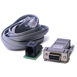
Dsc Pc Link Software Download Full
DSC version 1.2 was released on 27 January 2016 and is included in version 1.4 of the DisplayPort standard; DSC version 1.2a was released on 18 January 2017. The update includes native encoding of 4:2:2 and 4:2:0 formats in pixel containers, 14/16 bits per color, and minor modifications to the encoding algorithm.
- Download offline utilities related to Income tax returns/forms, DSC Management Software and Mobile App.
- Download Dsc Installation Manual 1616.
- View online or download PDF (633 KB) DSC PC6010 User manual. PC6010 security access control systems PDF manual download and more DSC online manuals.
- ℹ️ Download DSC PC 580 Manual (Total Pages: 20) for free in PDF. Find more compatible user manuals for your DSC PC 580 Software device.
| Device 1 Pin Number | Device 1 Pin Name | Direction | Device 2 Pin Number | Device 2 Pin Name | Description (may be empty) |
| 2 | RD | Receive | 4 | Serial Output | Serial Data from Alarm Panel - Red wire |
| 3 | TD | Transmit | 1 | Serial Input | Serial Data to Alarm Panel - Yellow Wire |
| 4 | DTR | Transmit | NC | Jumper to DSR | |
| 5 | SG | Ground | 2 | Ground | Signal Ground - Black |
| 5 | SG | Ground | 3 | Ground | Signal Ground - Black |
| 6 | DSR | Receive | NC | Jumper to DTR |
The Pin red and yellow may be inverted, the pin number 1 is the red and in the table Device 2 is set as 4, the Mini-Molex has the pin 1 in the red wire location?


Connect the Molex to the PC-Link connector on the alarm panels main board. Connect it so that the red wire is directly beside the 'SO' printed on the circuit board.
You will also need the DSC software. This will not work with just a ordinary comm. program
Dsc Pc Link Software Download
Wire colors at the header are immaterial since the PC-LINK is sold as a small circuit board with a female header, and any other implementation could use arbitrary colors. It is possible to connect the header wrong, which causes the SI and SO connections to be swapped. A silk-screened bar appears on the alarm board to suggest how to orient the header (so the header board is next to the silk-screened bar. Pin 1 of the header is the SI connection, pin 4 is the SO connection. SI and SO appear on some alarm boards next to the header, but not all boards have that.
Comments are closed.